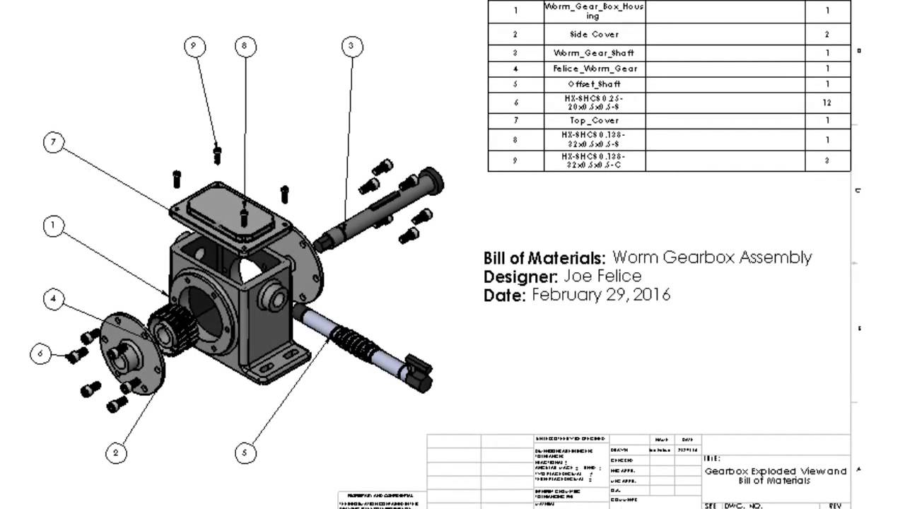
The exploded diagram of the worm gear box assembly. The parts are as

Download scientific diagram | The exploded diagram of the worm gear box assembly. The parts are as follows: 1-cover; 2-bearing; 3-worm shaft; 4-cover; 5-bearing; 6-gear box body; 7-bearing; 8-oil seal; 9-cover; 10-plug; 11-worm gear rim; 12-worm gear hub; 13-output shaft; 14-bearing; 15-oil seal; 16-cover from publication: Image-assisted collision detection for calculation of an assembly interference matrix | The assembly interference matrix is a foundational information model for assembly process planning such as assembly sequence and assembly path planning, and supports digital assembly simulation, intelligent assembly, digital twin-based assembly, and so on. The assembly | Collision Detection, Assembly and Matrix | ResearchGate, the professional network for scientists.
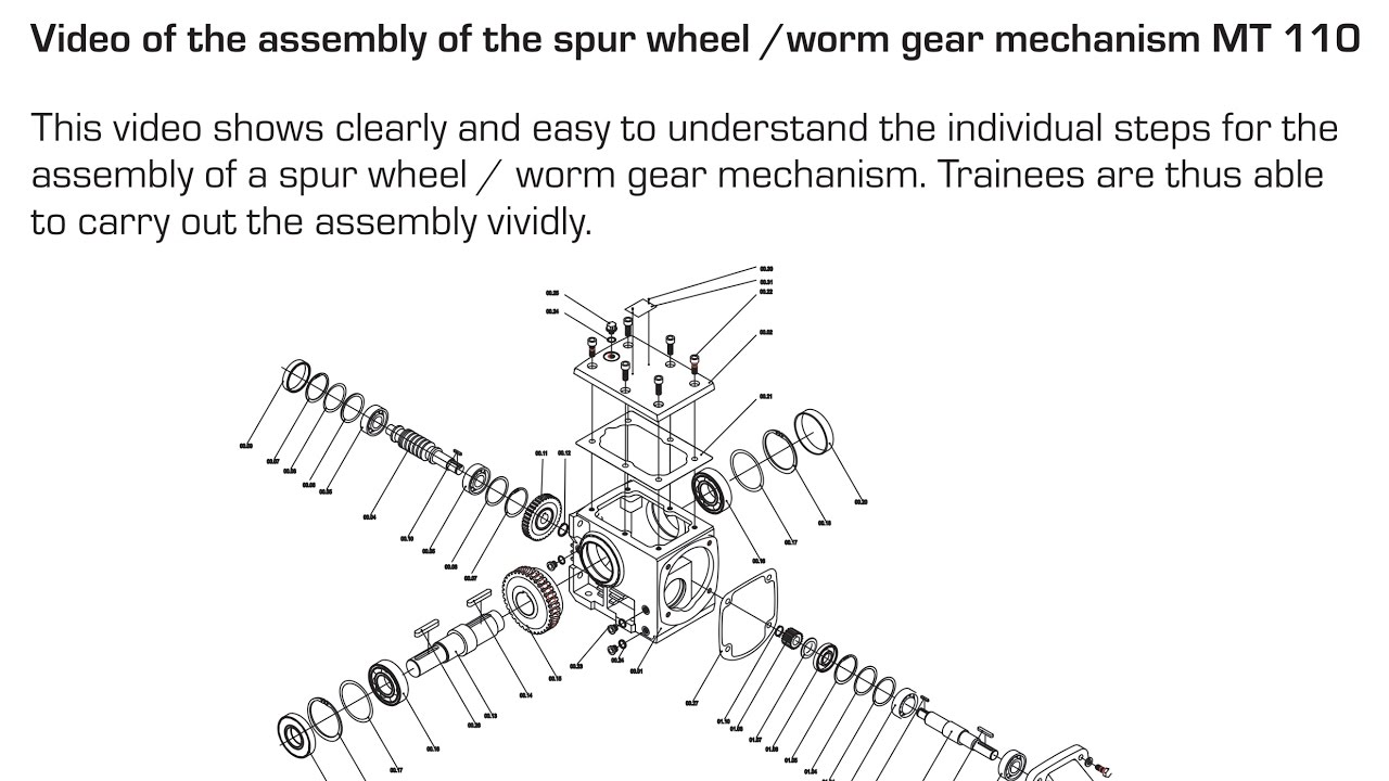
Assembly of the spur wheel /worm gear mechanism MT 110 EN
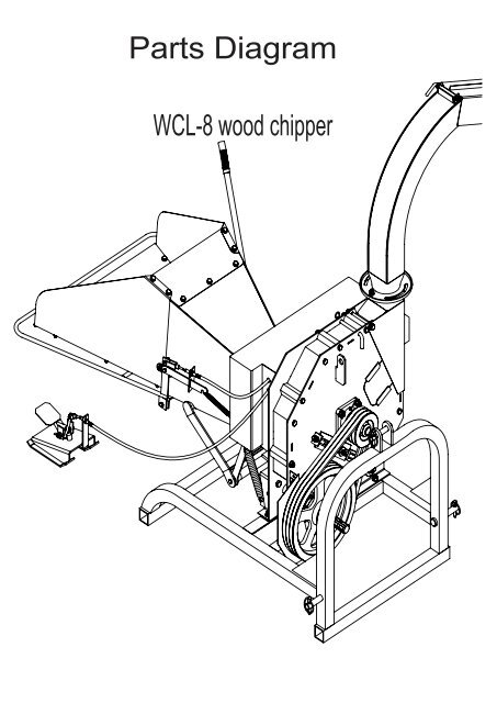
Parts Diagram - Chippers Direct

DC GEAR MOTOR/DC MOTOR Doncen Motor
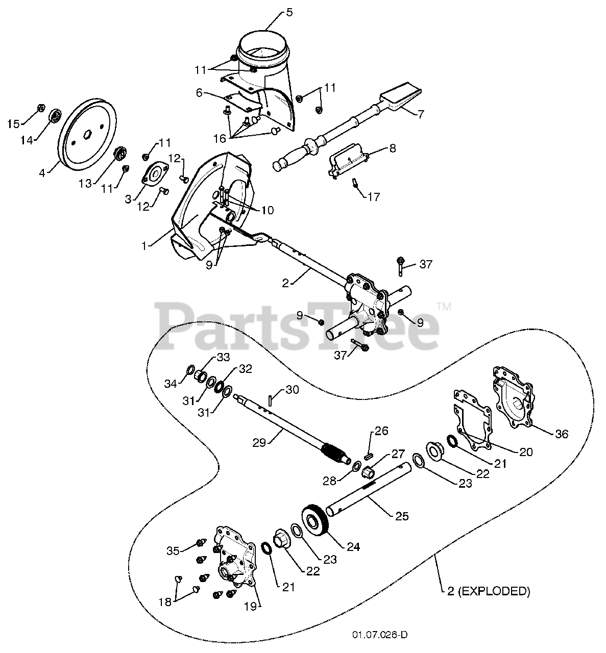
Troy Bilt 31AM5CP3766 Storm 2690 (2017) Parts Diagram for Chute Gearbox Assembly
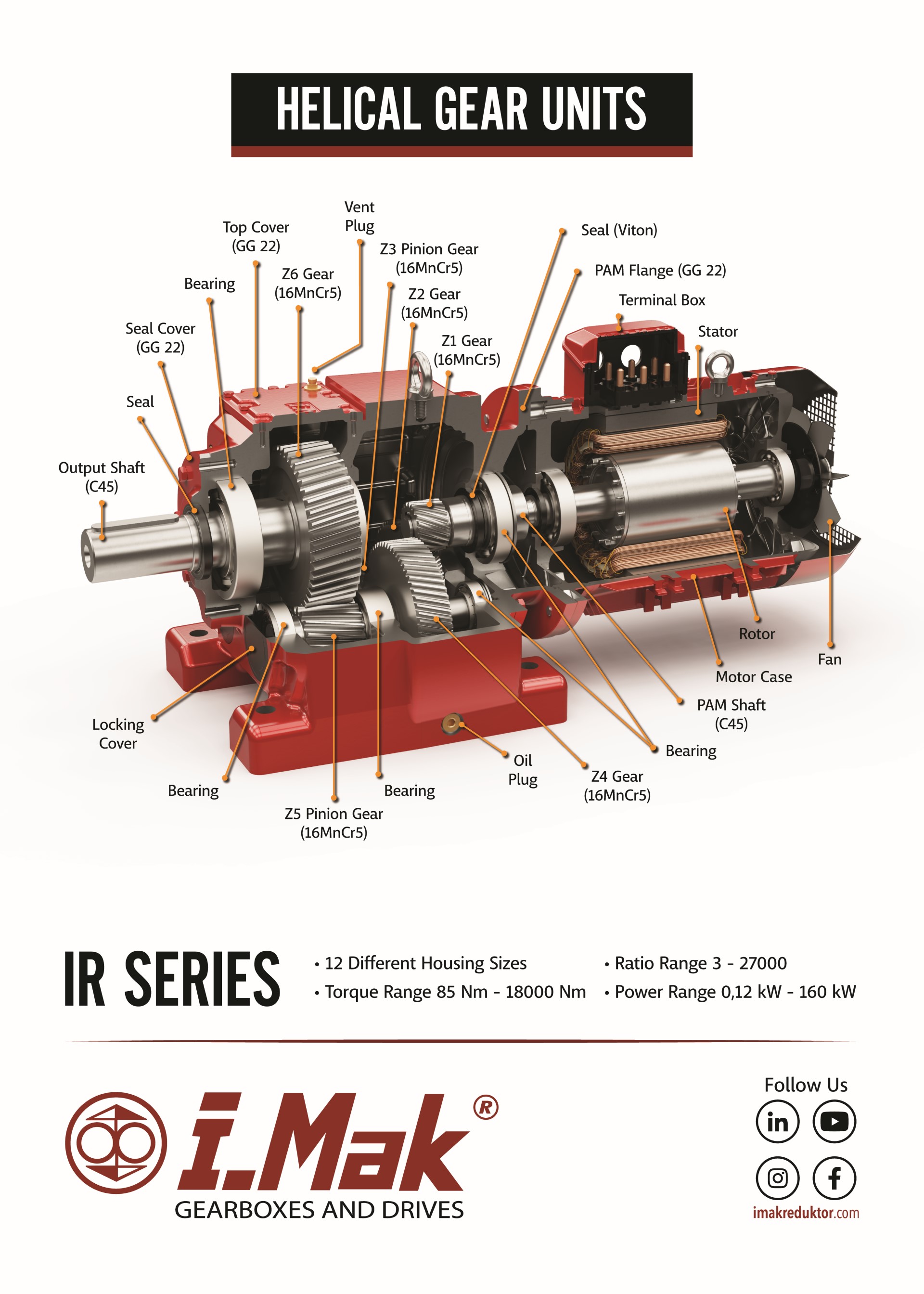
Spare Parts List, Gearbox Spare Parts are on - iMAK Gearbox

Tamiya Worm Gear Box

Layout of parts in the enveloping speed reducer: (1) right end cover;
Gearbox Motion Study and Drawings

Worm Gear Box Assembly Gearbox Wheel Speed Agricultural Planetary Helical Bevel Steering Gear Drive Motor Speed - China Gearbox, Gear Motor
Poulan Pro 961940009-01 - Poulan Pro Snow Thrower (2010-06) Auger Housing / Impeller Assembly Parts Lookup with Diagrams