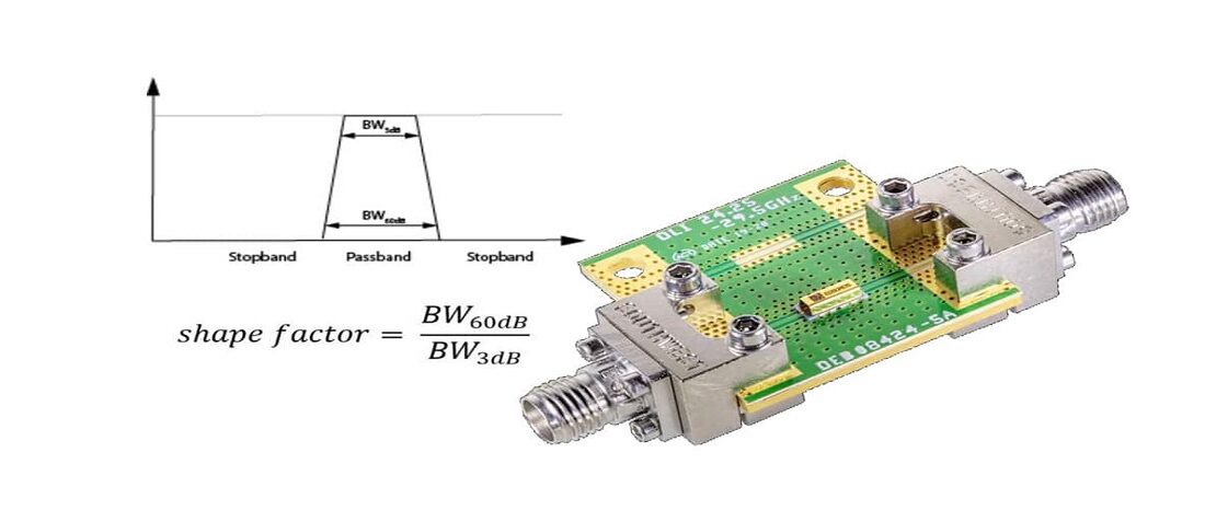
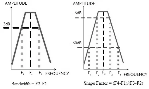
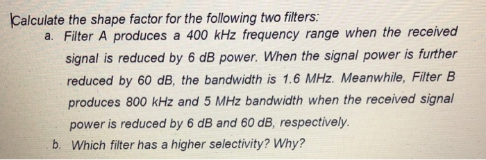
Filter Shape Factor and Selectivity
The Ideal Filter would have a unit gain (0dB) in its passband and a gain of zero (-infinity dB) in its stop band. Between the pass band and stop band, there would be no indecision and would transition from 0dB to -infinity dB asymptotically.

Passive Filter Design: High Q Factor and Low Loss

Home 2
Filter Shape Factor and Selectivity
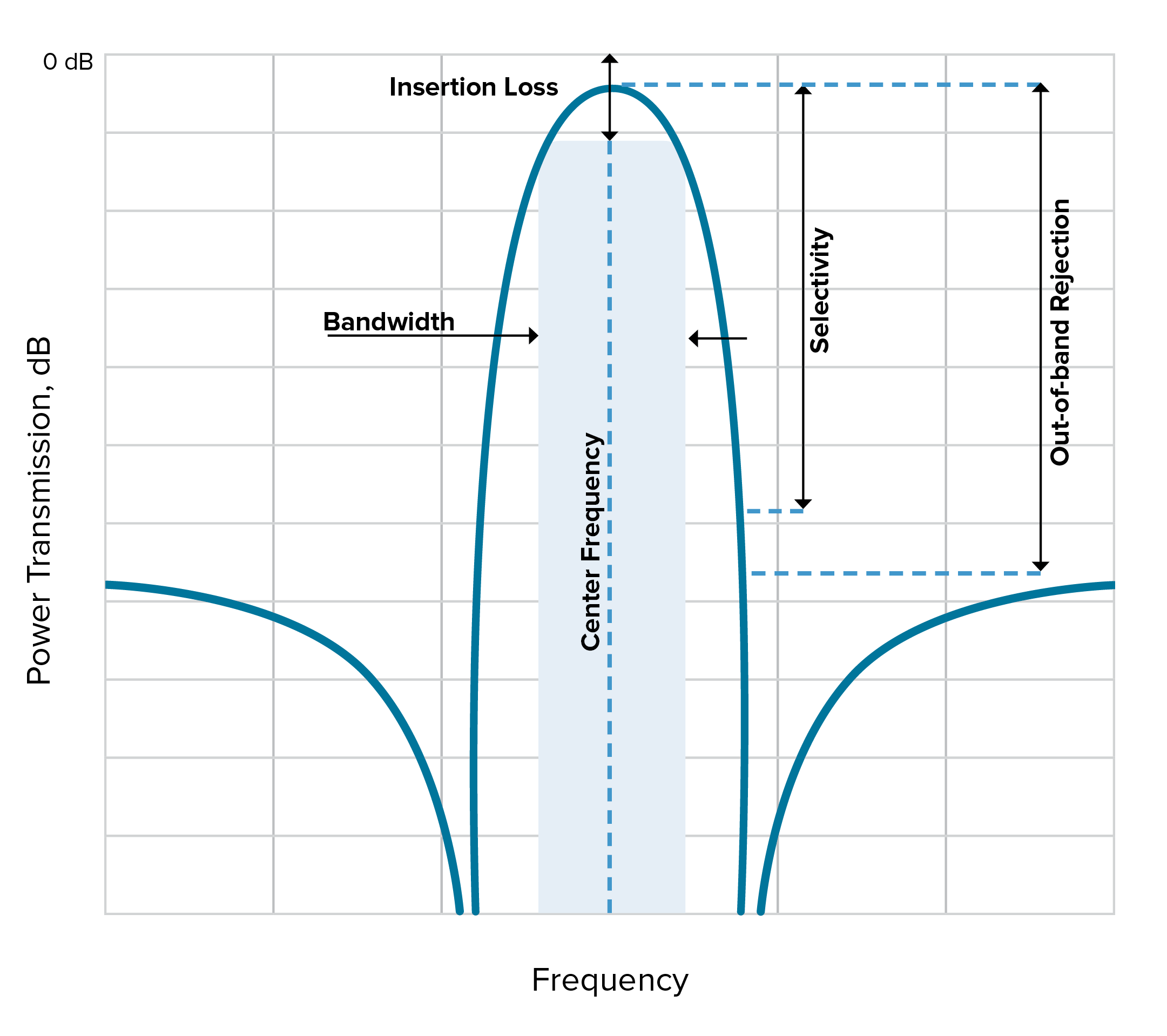
RF filter terminologies

Realization of dual-mode, high-selectivity SIW cavity bandpass filter by perturbing circular shape vias

Filters Archives - EEE Parts Database
/hs-fs/hubfs/Filter%20Ba
Solved Antenna AGC - V f fif rf RF Amplifier X IF Amplifier

The general frequency response shape of a bandpass filter.
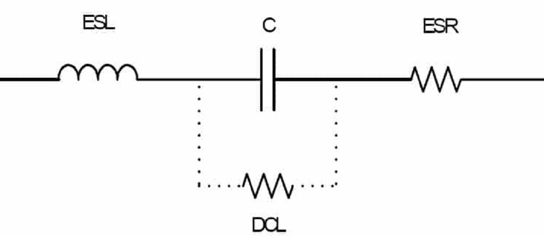
Leakage Current Characteristics of Capacitors - Case Study

How to Design High-Selectivity Low-Distortion Filter Circuits